
Harold Hall


The Bullwheel
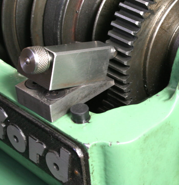
Many home workshop owners in the past have used the lathe mandrel by engaging a plunger with the back gear's bullwheel, Photograph 13. This is limited by the number of teeth on the gear and if this is not a convenient number may make it a non starter. Its uses will typically be for the lower numbers such as making hexagons or squares on components already in the chuck having been machined there, perhaps using a filing rest to produce the shape. The bullwheel is the gear fixed to the lathe's mandrel as part of the back gear assembly.
Mandrel mounted gear
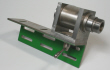
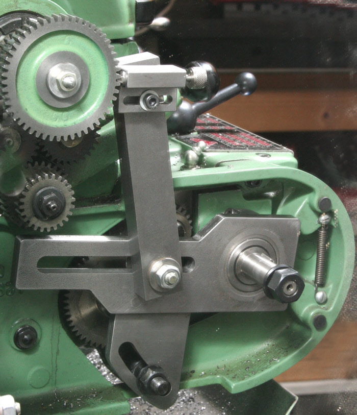
Mounting a gear on the rear end of the mandrel will prove more adaptable as any of the lathes change gears can be used providing a wide range of possibilities, Photograph 14. Using a dividing plate in a similar manner will expand the possibilities even further. The likely method for mounting the gear, or dividing plate, would be to use an expanding mandrel to grip the internal bore of the lathe's mandrel as illustrated in SK. 2.
Backplate dividing
A relatively common method, much used in the past, is to drill the periphery of the chuck's back plate with a series of holes to provide its own inherent dividing plate.
All three of the above methods will require some attachment to carry a locating plunger and, whilst the principle will be the same, the mechanics of doing this will vary from lathe to lathe. These three methods do have the advantage of locking the lathe mandrel so that light machining on the part can take place.
An Application.
Dials can most often be more easily made on the lathe, rather than the milling machine, as the top and cross slides enable depth and length of line to be set with ease, with the divisions being set, either using the method in photograph 12 or photograph 14. Alternatively, using a dividing head, if available, on the lathe's bed, as shown in Photograph 15 will increase the range of divisions available.
With the dividing head mounted in this way the top and cross slides can still be used as above but the photograph shows that for this set up my lining tool is being used to control the length of the line rather than the top slide. Details of the lining tool are given on other pages on the site.
The dividing head in the photograph is made with its centre height equal to the lathe’s centre height so that the tailstock could be used to support a component if necessary.
Metalworking
Workshop Processes

13

14


15