
Harold Hall
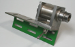
Return the Locking Spindle to the lathe (three jaw chuck) and place the Body onto it and fit and tighten the countersunk screw (H7). The Body should be loose allowing it to slide back and forward. Test the amount by inserting a test piece between the Locking Spindle head and the Body to determine how much has to be removed from the end of the spindle, Photo 28, reduce its length after removing the body.
A little end float though is perfectly acceptable so remove a little less than the test piece as you can always repeat the test and remove a little more if the end float is still considered excessive. I found that tightening the countersunk screw expanded the end of the spindle and it became a little tight. I had therefore to remove the Body and file a little off around the end of the spindle, you may find this necessary as I think it is highly likely as the screw does need to be well tightened.
Give the head a skim to achieve a good finish, part off, reverse, and face the end also giving it a chamfer and the machining work is now complete.
Assembly
Assemble the parts, not forgetting to include some lubrication in the appropriate places and it will be natural now to want to put the tool holder through its paces, which I did, and was completely happy with the result. However, there was something about it that I did not like compared to my originals, it was not pleasant to handle, I soon realised though that I still had to chamfer all the edges and round the corners. Not a small task with there being 12 holders needing the treatment, but it has to be done.
One very minor task is to centre punch the top of the Locking Spindle head so as to indicate its position when the clamp mechanism is fully open, I find this useful, see assembly drawing.
With that done it just needs all the screws to be fitted, don't forget though the pad of copper (H1) under the screw (H2). I have in the past use fine copper wire from a piece of flexible electrical cable and rolled it into a ball. This time though I chose what turned out to be an easier method. This was using thicker piece of copper wire, about 0.5mm diameter and with a very small pair of round nose pliers wound what looked like a spring of say two turns, cut it off and dropped it into the hole.
Tighten the grub screw (H2) until screw (H3) becomes stiff to turn, after some time the copper may relax a little and the grub screw tightened once more.
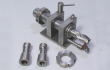
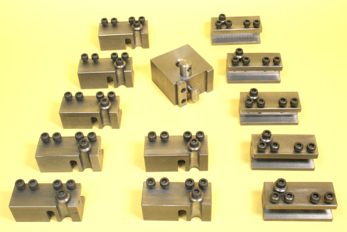
With that done, the holders are available for use, I hope you find them as useful as I have done with my Mk1 holders and expect to do with the Mk2 version. Photo 29, shows the completed set.
Metalworking
Workshop Projects


28
29


DRAWINGS
Lathe only workshop
The next page gives ideas for the workshop owner who does not have a milling machine